So, in the first part of the DIY cash register toy I introduced the parts which will be used for the cash register.
Now, I will do test with the Rfid reader I already owned and the thermal printer which I bought and which arrived at first…
The Rfid reader
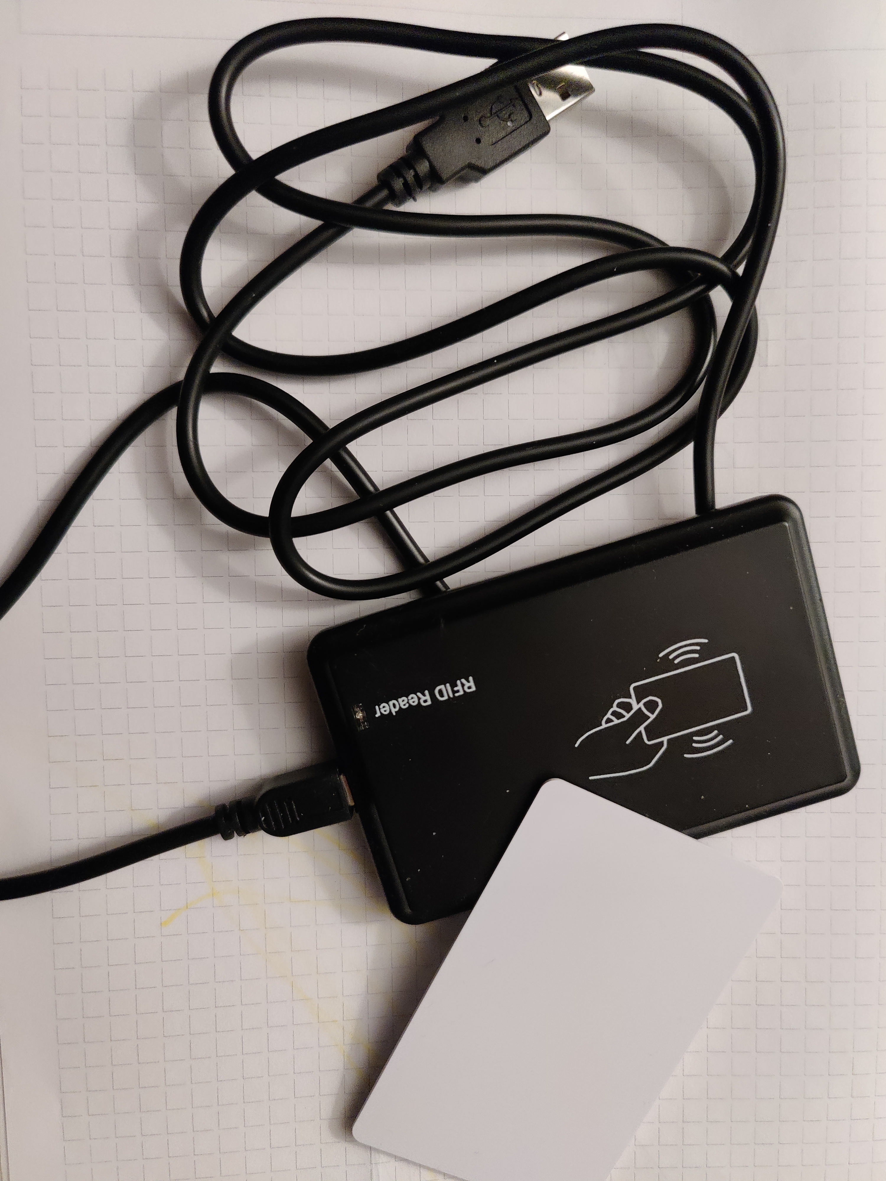
I bought the Rfid reader from AliExpress some time ago. Originally I bought it for my DIY Media Player Box, but I couldn’t use it, because it only reads the code once. It behaves like an ordinary keyboard.
But in this case, this is exactly the behaviour I need…
So, here is a picture of it:
If you connect it to USB, and type this in your terminal:
| |
You will get this (somewhere in between the other output):
| |
So, it is recognised, great!
Like said, it behaves like an ordinary keyboard, so you will find it under /dev/input/. It will have a name like eventXX, where XX is a number.
But how to get the right one? And how to utilize the reader?
For that I wrote a small GO util application: https://github.com/pmoscode/diy-cash-register-toy/tree/main/input-reader
This application can help you to get the right event and to get the data from the reader (You will need the name which “lsusb” provides you). As an addition, when you have a mqtt broker configured, you can provide the host and topic to the application, and the read code will be sent there.
That’s all for the Rfid reader. Now, the thermal printer will be tested…
The Thermal printer
The Thermal Printer is a funny little thing. You can print almost “everything” in b&w…
Here it is, how it looks like:
Wiring
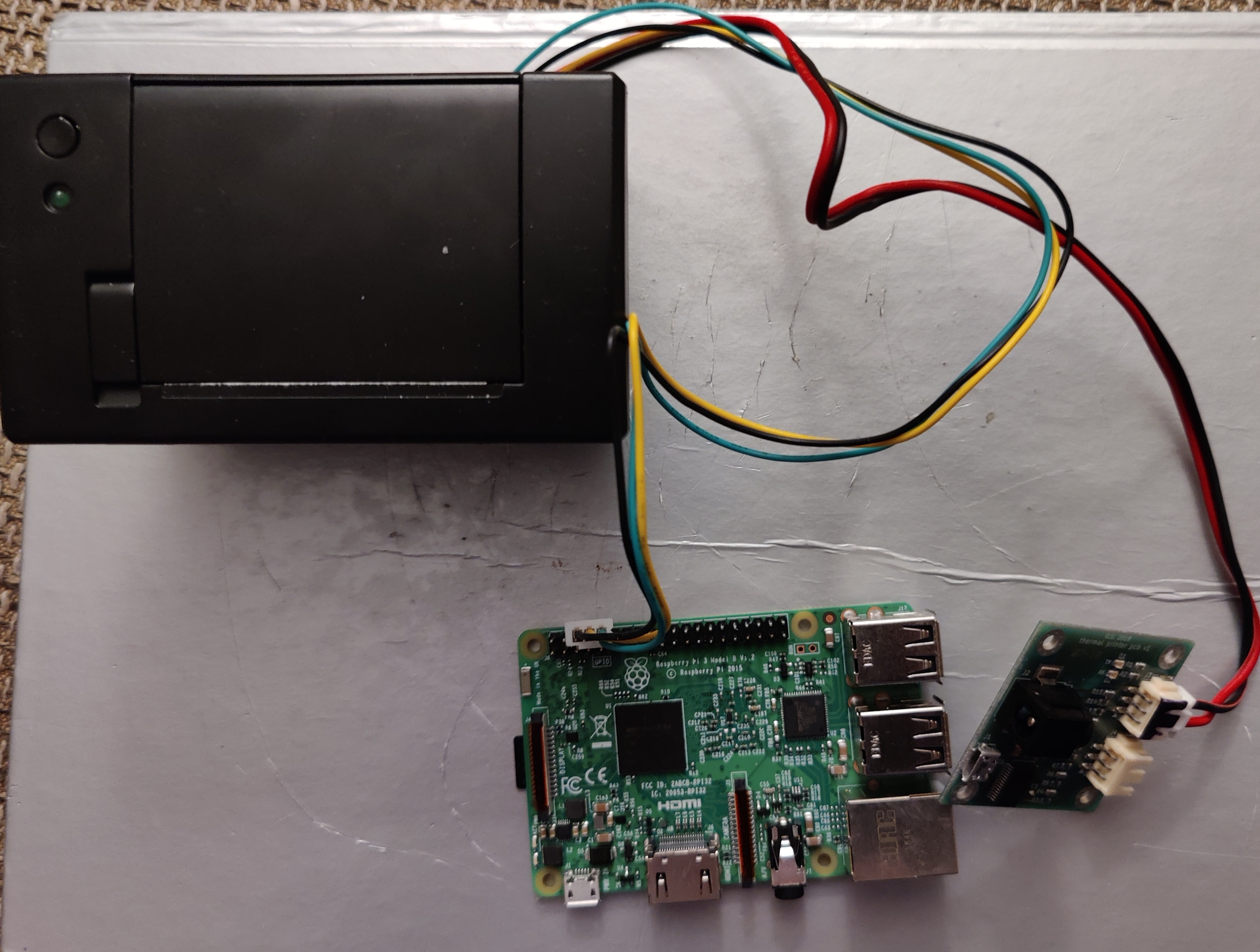
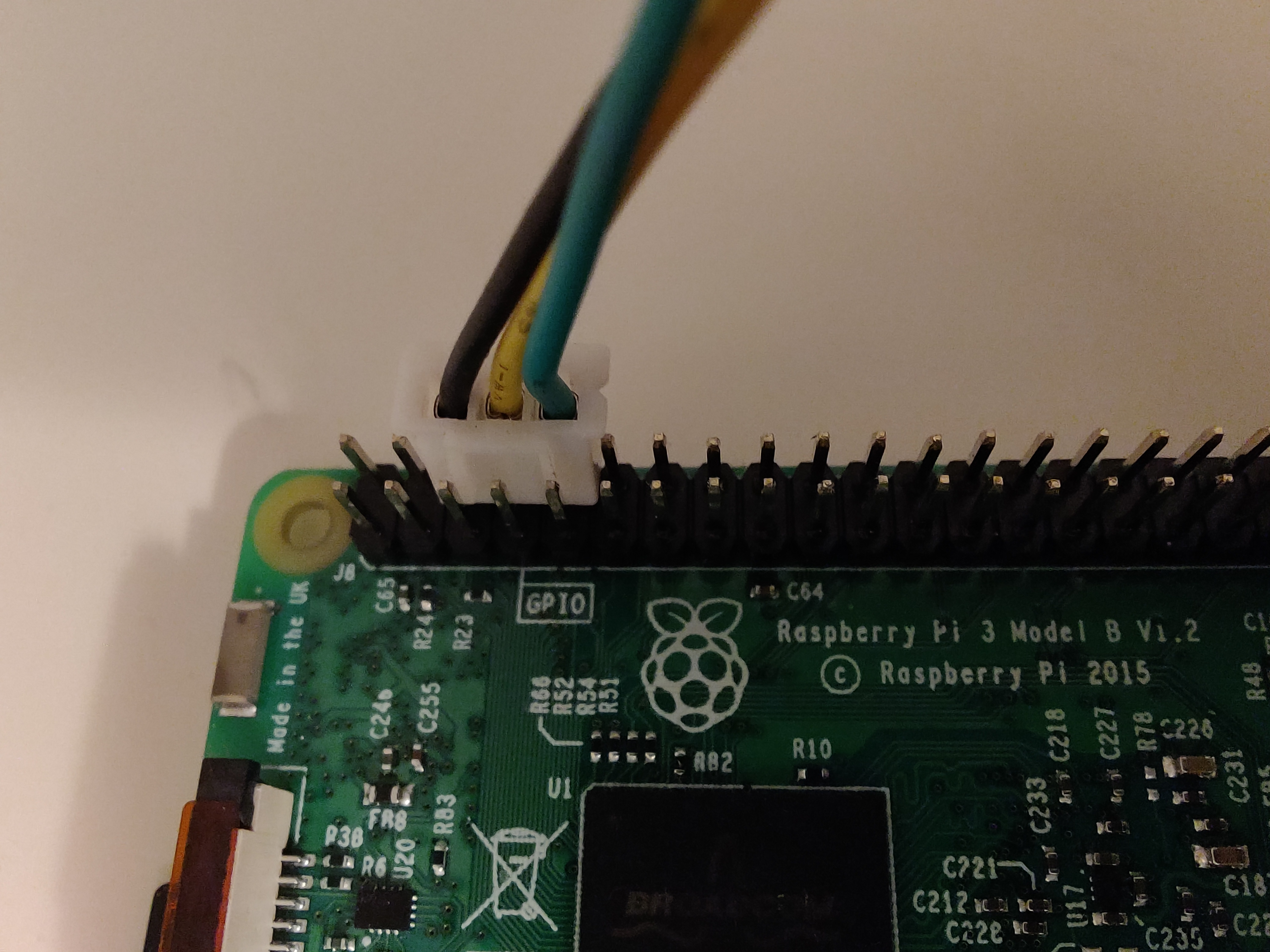
The printer came with a power adapter and a controller PBC. The PCB has a USB port, so it’s possible to connect it there.

But in my case, the USB didn’t work. I couldn’t figure out why and how to fix it. So, I used the direct connection to the printer (via the three wires - black, green and yellow). It’s a serial connection, which is perfect for the Raspberry Pi. I also could wire it without the need to cut the wires:
Configuration
Now that the wiring is done, the Raspberry Pi needs to be configured.
First, you need to enable the Serial Console:
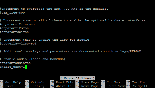
Via /boot/config.txt
Edit the /boot/config.txt on the SD card directly with
| |
At the bottom, last line, add the line enable_uart=1.
Via raspi-config
Connected to the Raspberry Pi, run
| |
Go down to Advanced Options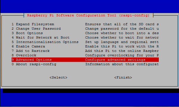
Then go down to Serial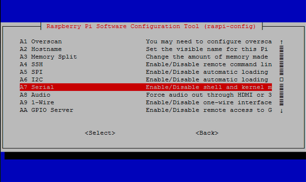
Then select Yes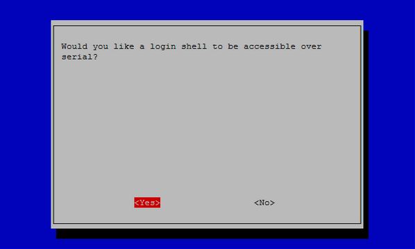
It should be enabled now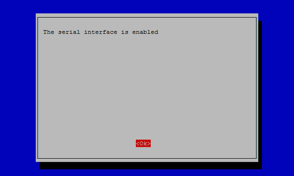
When it asks you to reboot, go to Yes, and you’re done with the first configuration part.
Now it’s time to test the printer…
Testing
When the Raspberry Pi is rebooted, connect to it. You should now get an additional device in /dev, like /dev/serial0
But before you can send text to the printer, you have to configure the serial speed with
| |
Where 19200 is the baud rate. It may vary, if you have a different thermal printer.
After that is done, you can send text to the printer now:
| |
Et voilà!
In the next article I will show how to print graphics with that printer.
Ah, and last but not least, here is the printer in action (with a sneak peek on the graphics):